Entity-Relationship (ER) diagrams are visual tools used to model and design the structure of a database before implementation.
In backend application development, ER modeling helps represent real-world objects as entities, their properties as attributes, and the associations between them as relationships.
This approach provides a clear blueprint for how data is organized and how different parts of the application interact through the database.
By using ER diagrams, developers and designers can plan database schemas that are logical, scalable, and easy to maintain.
Proper schema design based on ER modeling reduces redundancy, enforces data integrity, and simplifies future changes as application requirements evolve.
Understanding ER Diagrams
ER diagrams are graphical tools that represent the structure of a database at a high level, focusing on entities, attributes, and relationships before diving into tables and columns.
They originated from Peter Chen's 1976 paper and remain a cornerstone of database design, endorsed by standards like those from the ISO and IEEE for information modeling.
Core Components of ER Diagrams
At their heart, ER diagrams use three primary building blocks: entities, attributes, and relationships. Think of entities as nouns in your application's domain—like "User" or "Order"—while attributes describe their properties, and relationships define how they connect.
1. Entities: Real-world objects or concepts, represented as rectangles. Examples include Customer, Product, or Order in an e-commerce app.
2. Attributes: Descriptive properties of entities, shown as ovals connected to their entity. Key types include:
3. Relationships: Associations between entities, depicted as diamonds. They specify cardinality (how many instances relate), like one-to-many or many-to-many.
Keys are Crucial: Primary keys (underlined ovals) uniquely identify entities (e.g., user_id), while foreign keys link relationships.
Cardinality and Participation
Cardinality defines the numerical relationship between entities, guiding how your schema handles data integrity.
Participation indicates whether an entity must be involved (total, double line) or can be optional (partial, single line).
Building an ER Diagram Step by Step
Creating an ER diagram follows a structured process, much like sketching wireframes before coding a frontend.
This method ensures your model is normalized and scalable, reducing anomalies during CRUD operations in your backend APIs.
Step-by-Step ER Modeling Process
Follow these numbered steps to model any application domain, from a blog platform to a healthcare system.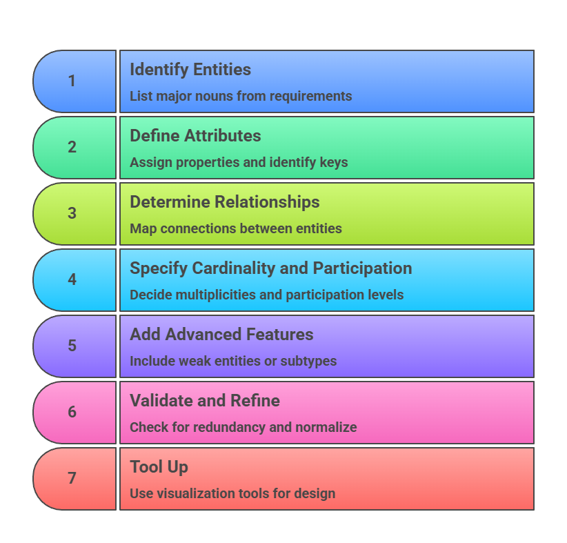
Example: For a simple ride-sharing app:
Entities: Driver, Rider, Trip.
Relationship: Driver drives Trip (1:N); Rider books Trip (N:1).
This prevents data duplication, e.g., storing driver details once.
From ER Diagram to Relational Schema
ER diagrams aren't just sketches—they directly map to SQL tables, forming the blueprint for your backend database.
Industry best practices from Oracle and PostgreSQL docs emphasize converting ER models to schemas early, ensuring ACID compliance and query optimization.
Mapping Rules: Entities to Tables
Transform your diagram systematically:
1. Strong Entities become tables with primary keys.
2. Weak Entities get tables with foreign keys to their owner.
3. 1:1 or 1:N Relationships: Add foreign key to the "many" side.
4. N:M Relationships: Create a junction table with foreign keys from both sides.
Consider this ER-to-schema example for an e-commerce app
ER Snippet
Customer (1) — places (N) — Order
Order (N) — contains (M) — Product (N:M)
Resulting Schema (SQL DDL)
CREATE TABLE Customer (

    customer_id SERIAL PRIMARY KEY,

    name VARCHAR(100),

    email VARCHAR(100) UNIQUE

);


CREATE TABLE Order (

    order_id SERIAL PRIMARY KEY,

    customer_id INT REFERENCES Customer(customer_id),

    order_date TIMESTAMP

);


CREATE TABLE Product (

    product_id SERIAL PRIMARY KEY,

    name VARCHAR(100),

    price DECIMAL(10,2)

);


CREATE TABLE Order_Product (  -- Junction for N:M

    order_id INT REFERENCES Order(order_id),

    product_id INT REFERENCES Product(product_id),

    quantity INT,

    PRIMARY KEY (order_id, product_id)

);
Handling Complex Cases
1. Advanced Scenarios: require careful design to maintain performance.
2. Multivalued Attributes: New table, e.g., Customer → Customer_Phone (customer_id FK, phone).
3. Subtypes/Supertypes: Use single table inheritance or class table (e.g., Employee supertype with Manager/Developer subtypes via discriminator column).
Best Practice: Always index foreign keys for fast JOINs in your FastAPI/Django endpoints.
Best Practices and Common Pitfalls
Solid ER design separates great backends from brittle ones, aligning with modern standards like those in ANSI SQL.
Apply these to future-proof your schemas for cloud deployments on AWS RDS or Supabase.
Key Best Practices
1. Start High-Level: Model business rules first, not tech constraints.
2. Normalize Early: Aim for 3NF to eliminate redundancy (e.g., no transitive dependencies).
3. Document Everything: Annotate diagrams with business rules.
4. Iterate with Stakeholders: Validate with product teams.
5. Version Control: Store diagrams in Git alongside schema migrations (use Alembic for Python).
Pitfalls to Avoid
1. Over-normalizing (hurts read performance—denormalize for analytics).
2. Ignoring nullability (use NOT NULL for required fields).
3. Forgetting indexes on frequent JOINs.
Real-World Tip: In a SaaS dashboard app, model User → Subscription (1:1) to handle upgrades without schema changes.
Tools and Integration for Backend Devs
Leverage these for seamless workflow:
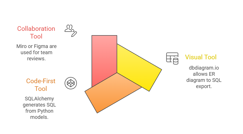
This ensures your ER diagrams feed directly into CI/CD pipelines.

Class Sessions
Sales Campaign

We have a sales campaign on our promoted courses and products. You can purchase 1 products at a discounted price up to 15% discount.